Friday, August 6, 2010

Structural combinations of the 4 ccp lattices

Structural combinations of the 4 ccp lattices

These structural combinations can be of the same or different atoms and of the same or different sizes. In the presentation to follow all atoms are at the vertices, and all vertices are occupied. This becomes an alternative system to identifying unit cells.


1.
The four ccp lattices: A, B, C, or D.


2. Combinations of A+B or C+D are the Simple Cubic (sc) structure or NaCl type structure. All of each others octahedra voids are filled. We have octahedral coordination, which is the alternative unit cells for simple cubic. A+B and C+D are two distinct simple cubic lattices that are topologically the same.


3. Combinations of A+C, B+C, A+D, or B+D are the cubic Diamond and related structures or ZnS structure. Half of each others tetrahedra are filled, A fills the negative tetrahedra of C and C fills the positive tetrahedra of A. We have tetrahedral coordination. There are four distinct diamond lattices that are topologically the same.


4. Combinations of A+(C+D), B+(C+D), (A+B)+C or (A+B)+D are the fluorite (AX2) CaF2 and the antifluorite (A2X) Na2O structures. Half of the (C+D) simple cubic are filled or all of A's or B's tetrahedra are filled, and half of the (A+B) simple cubic are filled or all of C's or D's tetrahedra are filled. It can also be seen as two interpenetrating diamond lattices like A+(C+D) as combination of diamond lattices (A+C) and (A+D).


5. Combinations of A+B+C+D are the body centered cubic structure. All tetrahedra and octahedra are filled, or (A+B)+(C+D) the CsCl structure (two simple cubic), (A+C)+(B+D) or (A+D)+(B+C) viewed as two interpenetrating diamond structures.


1. The Cubic Closest Packed Structure
A, B, C, or D


Elements:
Al, Ca, Cu, Ni, Sr, Rh, Pd, Ag, (Ce), (Tb), Ir, Pt, Au, Pb, Th

See (Fig.5a, 5b, 5c, or 5d)


Compounds:
Cu3Au, AlNi3 (others?). See (Fig. 20b) under Compound ccp lattice (Cu3Au)


2. The Simple Cubic Structure or NaCl Structure

A+B or C+D


Elements:
Alpha Po


Compounds:
NaCl, AgCl, BaS, CaO, CeSe, DyAs, GdN, KBr, LaP, LiCl, LiF, MgO, NaBr, NaF, NiO, PrBi, PuC, RbF, ScN, SrO, TbTe, UC, YN, YbO, ZrO (Ref. 4)


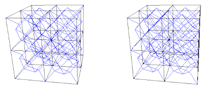
Fig. 6a. Combination A+B. 3 frequency simple cubic or 27 sc unit cells. A in red, and B in blue.


Fig. 6b. Combination C+D. 2f or 8 unit cells. C in red, and D in blue.


3. The Cubic Diamond Structure or ZnS Structure
A+C, B+C, A+D, or B+D


Elements: C (diamond), Si, Ge, Sn (grey)


Compounds: ZnS, AgI, AlAs, AlP, AlSb, BAs, BN, BP, BeS, BeSe, BeTe, CdS, CuBr, CuCl, CuF, CuI, GaAs, GaP, GaSb, HgS, HgSe, HgTe, InAs, InP, MnS, MnSe, SiC, ZnSe, ZnTe (Ref. 4)


Fig. 7a. Combination A+C. Diamond net (blue) interconnecting the A and C lattices.


Fig. 7b. Combination B+C. Diamond interconnecting net not shown.
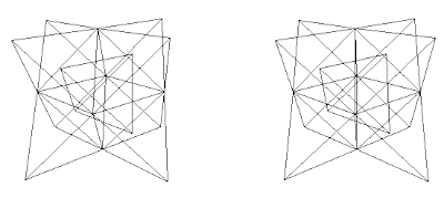


Fig. 7c. Combination A+D. Diamond interconnecting net in blue.
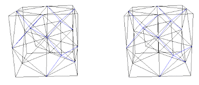


Fig. 7d. Combination B+D. Diamond interconnecting net in blue.


Fig. 7e. Diamond net, 4 unit cells. Traditional view. Combination A+C.

Fig. 7f. Diamond structure, same as (Fig. 7e). It is the combination A+C with A in blue. The interconnecting diamond net is not shown.


4. The Fluorite (AX2) and Antifluorite (A2X) Structures
A+(C+D), B+(C+D),
C+(A+B) or D+(A+B)

Elements: ? (There should be elements with this structure, unless this is an exception)

Compounds: CaF2,AmO2, AuAl2, AuIn2, BaF2, Be2B, CdF2, CeO2, CoSi2, EuF2, HgF2, Ir2P, Li2O, Na2O, NiSi2, PtAl2, Rb2O, SrCl2, SrCl2, SrF2, ThO2, ZrO2 (Ref. 4)


Fig. 8a. Traditional view of fluorite structures. CaF2 as shown on pg. 252 (Ref. 3) and pg. 52 (Ref. 5). This is a C+(A+B) combination, where Ca = (C) and F = (A+B) as shown in (Fig. 8b)
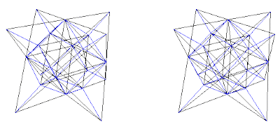


Fig. 8b. Combination C+(A+B). CaF2 shown in traditional view in blue with Ca = C lattice and F = (A+B) lattices. Cube outline is not shown.
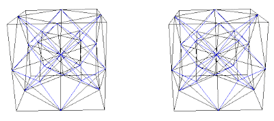


Fig. 8c. Combination D+(A+B) with interconnecting blue net.
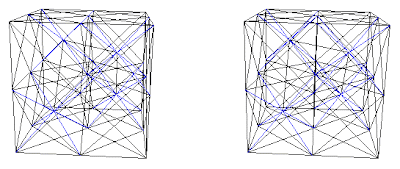


Fig. 8d. Combination A+(C+D) with interconnecting blue net.
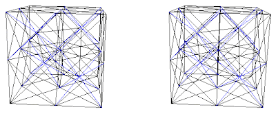


Fig. 8e. Combination B+(C+D) with interconnecting blue net.


Fig. 8f. Fluorite of 8 unit cells. They are cubic closest packed rhombic dodecahedra. This is a C+(A+B) view.


5. Body Centered Cubic Structures
A+B+C+D
(A+B)+(C+D)
(A+C)+(B+D) or (A+D)+(B+C)

Elements: W, Li, Na, K, V, Cr, Fe, Rb, Nb, Mo, Cs, Ba, Eu, Ta

Compounds:

  • CsCl, CsBr, RbCl, AlCo, AgZn, BeCu, MgCe, RuAl, SrTl (Ref. 4)
  • NaTl, LiZn, LiCd, LiAl, LiGa, NaIn, (pg 1301, Ref. 3)
  • Fe3Al, Li3Bi, Li3Sb, Li3Pb, (pg 1301, Ref. 3)
  • AlCu2Mn, AlNi2Ti, AlNi2Hf (Ref. 4)


CsCl has structure of type (A+B)+(C+D) with A=Cs, B=Cs, C=Cl, and D=Cl, or (Cs+Cs)+(Cl+Cl)


Fig. 9a. CsCl structure with traditional view.
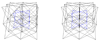


Fig. 9b. CsCl structure, (A+B)+(C+D). With (A+B) in blue.

Fig. 9c. NaTl with combination of (A+B)+(C+D) as (Na+Tl)+(Tl+Na). Tl is shown in blue. Also shown is the partial tetrahedral axial view, or the two interpenetrating diamond view, or (A+C)+(B+D) view on the upper right corner.
The above is the same view as (Fig. 29.12), pg 1301 (Ref. 3).
The 2 interpenetrating diamond view of (A+C)+(B+D) (Ref. 4) or to view in 3D go to: The NaTl (B32) Structure


Fig. 9d. Fe3Al with combination of (A+B)+(C+D) as (Al+Fe)+(Fe+Fe) with Al shown in blue.
Same as shown in pg. 1298, fig. 29.10 (b) (Ref.3)

Cs3Sb has the same structure as Fe3Al with ((Cs/Sb)+Cs)+((Cs/Sb)+Cs) where (Cs/Sb) are equal numbers of Cs and Sb occupying sites A and C at random. From pg. 1301, (Ref. 3).

I just realized that the above coincides with Table 29.7, Structures of the CsCl-NaTl family, pg. 1302 (Ref. 3), in a way the atom positions Wells identified as A, B, C, and D corresponds exactly to the lattices A, B, C, and D used here. His chart includes in addition: Li3Bi, Bi2OF4, NaY3F10. Li3Bi shown in chart as A=Bi, B=Li, C=Li, D=Li it would translate to (A+B)+(C+D) as (Bi+Li)+(Li+Li) same as (Fig. 9d), Bi2OF4 shown in chart as A=4 Bi, (B,C,D)=2 O + 8 F, is not sufficient information to translate. NaY3F10 shown in chart as A=Na, 3 Y, (B, C, D)=10 F, from fig. 9.7, pg 422, translates to (A+B)+(C+D) as ((Na, 3 Y)+F)+(F+F) where Na occupies a tetrahedral vertex and 3 Y occupy the other three vertices of the tetrahedron.
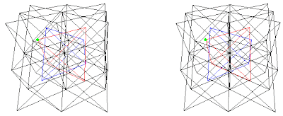


Fig. 9e. NaY3F10 in the combination (A+B)+(C+D) where Na in green and Y in red are A, F in blue is B, and F also occupy C and D lattices in black.
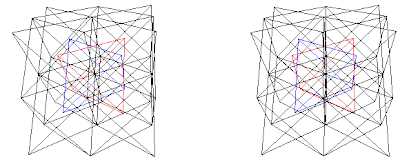


Fig. 9f. AlCu2Mn (A+B)+(C+D) (Al+Mn)+(Cu+Cu), Al is red and Mn is blue, from (Ref. 4) or to view in 3D go to: The Heusler (L21) Structure
Monday, August 2, 2010

Evolution 1985-2003


The Pattern of Patterns

Structural combinations from 4 IVM (fcc) to Bcc lattices

from A, B, C, D to A+B+C+D

Last update 2-24-2003

(This is a Chart of the pattern of patterns)


I. Combinations of 4 IVMs (A, B, C, D)


[Combinations of 2, tetrahedral edges]
1a. 2 Cubic nets

A+B

AB+CD 2 interpenetrating cubic nets (bcc)

C+D


1b. 4 Diamond nets


A+C = AC

B+C = BC

A+D = AD

B+D = BD

[Combinations of 3, tetrahedral faces]

2. 4 Rhombic Dodecahedral nets ABC, ABD, ACD, BCD ivm (see II-1b below)


A+B+C = ABC

A+B+D = ABD

A+C+D = ACD

B+C+D = BCD


3. Combination of (I-1a), 2 cubic nets

AB+CD = 2 interpenetrating cubic nets = bcc lattice


II. Combinations of 4 Diamond nets (AC, BC, AD, BD) [I-1b]

[Combinations of 2]
1a. Two Interpenetrating Diamond nets

AC+BD

ACBD+BCAD 4 interpenetrating diamond nets (bcc)

BC+AD


1b. 4 Rhombic Dodecahedral nets (RD nets), (see I-2)

AC+BC = D’ RD net = ABC ivm

AD+BD = C’ RD net = ABD ivm

AC+AD = B’ RD net = ACD ivm

BC+BD = A’ RD net = BCD ivm


[Combinations of 3]
2. 4 Half-filled RD nets (of 3 diamond combinations)

AC+BC+BD = D’ RD net ½ filled by BD

AD+BD+AC = C’ RD net ½ filled by AC

AC+AD+BC = B’ RD net ½ filled by BC

BC+BD+AD = A’ RD net ½ filled by AD


3. Combination of (II-1a), 2 interpenetrating diamond nets

ACBD+BCAD = 4 interpenetrating diamond nets = bcc


III. Combinations of 4 RD nets (ACBC, ADBD, ACAD, BCBD) [II-1b]


[Combinations of 2]

1a. 2 Coupler nets


ACBC+ADBD = D’+C’= odd coupler

ACBC,ADBD+ACAD,BCBD =“Siamese Couplers”

=2 interpenetrating coupler nets = RITE net = (bcc)

ACAD+BCBD = B’+A’= even coupler


1b. 4 Half-filled RD nets (of 2 RD combinations), note the filling difference between III-1b and II-2

D’+B’ = ACBC+ACAD = D’ RD net ½ filled by AD

C’+A’ = ADBD+BCBD = C’ RD net ½ filled by BC

C’+B’ = ADBD+ACAD = B’ RD net ½ filled by BD

D’+A’ = ACBC+BCBD = A’ RD net ½ filled by AC


[Combinations of 3]
2. 4 Three RD nets (degenerated? into pairs of odd and even coupler nets)

A’B’C’ = BCBD+ACAD+ADBD = 2 interpenetrating RD, B’+A’= even coupler net (ADBD is redundant)

A’B’D’ = BCBD+ACAD+ACBC = 2 interpenetrating RD, B’+A’= even coupler net

A’C’D’ = BCBD+ADBD+ACBC = 2 interpenetrating RD, D’+C’= odd coupler net

B’C’D’ = ACAD+ADBD+ACBC = 2 interpenetrating RD, D’+C’= odd coupler net


3. Combination of (III-1a), 2 coupler nets

ACBC,ADBD+ACAD,BCBD = 2 interpenetrating coupler nets = RITE net = bcc


IV. Combinations of 4 Half Filled RD nets [III-1b]


1a.

1b.

2.

3.


I. Combinations of 4 IVMs (A, B, C, D)


[Combinations of 4]
3. Combination of all 4 IVMs

A+B+C+D = 4 IVM = bcc, including all the above pattern combinations.


Notes on main patterns:


  • The various patterns obtained through the possible combinations of the 4 IVMs or 4 fcc lattices are limited between the fcc lattices and the bcc lattice.
  • With 4 different lattices we can have a total combination of 6 pairs. And they are differentiated into two groups, group 1a with 2 combinations and 1b with 4 combinations.
  • The 2 pairs in I-1a, II-1a, III-1a, are always complementary, and their combination lead directly to the final stage the bcc lattice.
  • The 4 pairs in I-1b, II-1b, III-1b, are the new 4 lattices that can combine in the same way as the previous 4 lattices.
  • I do not know if this repeating pattern goes on indefinitely, it appears that at III-2 we start seeing a redundancy where it suggest an end to the 4 pairs pattern. The 4 pairs become in essence 2 pairs due to redundancy.

Mapping the Hidden Patterns in Sphere Packing(4)

Mapping the Hidden Patterns in Sphere Packing

by Russell Z Chu


Combination of all 4 fcc lattices

This is the last combination. We started by identifying the 4 fcc lattices and showed all the possible combinations, the six combinations of 2 fcc lattices and the four combinations of 3 fcc lattices. This is the combination of all 4 fcc lattices, making a total of 11 combinations.

The combination of 4 interpenetrating fcc lattices or all of the fcc lattices together is the body center cubic lattice (bcc). It is the combination of the 4 fcc lattices with the 2 cubic nets and the 4 diamond nets or 4 rhombic dodecahedron nets, all together.


Different views of the bcc lattice


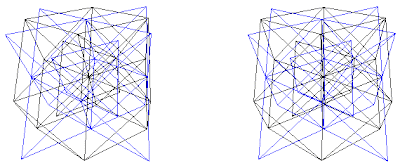
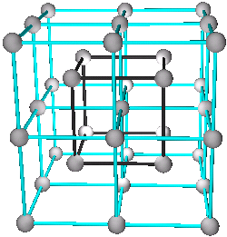
Figure 24a. The 4 fcc lattices.

Figure 24b. The 2 cubic nets.


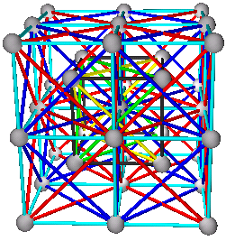
Figure 25a. The 4 fcc lattices with the 2 interconnecting cubic nets.


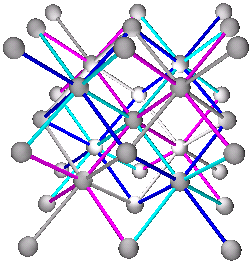
Figure 25b. The 4 diamond nets or 4 interpenetrating rhombic dodecahedron nets.


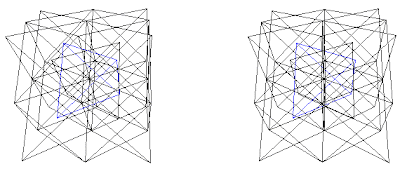
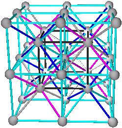
Figure 26a. The 2 cubic nets with the 4 diamond nets (which are the same as the 4 rhombic dodecahedral nets.)


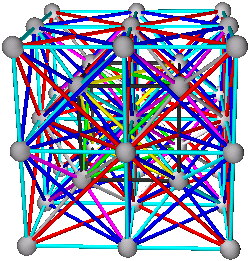
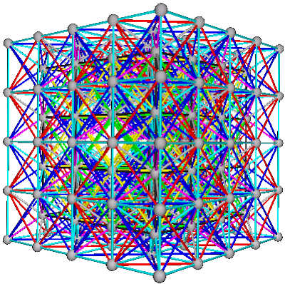
Figure 26b. The body center cubic lattice with all of the 4 fcc lattices and the interconnecting nets.


Figure 27a. The ‘coupler’ net is another possible view of the bcc lattice.

Figure 27b. This is one view of the ‘syte’ net.


Richard Hawkins has pointed out that Fig. 27b is one of the modules that Fuller named ‘SYTE’ (SYmetrical TEtrahedron) and that this particular syte is named ‘RITE’.

The coupler and syte are part of Fuller’s allspace-filling quanta module system. ”All the geometries in the cosmic hierarchy (see Table 982.62) emerge from the successive subdividing of the tetrahedron and its combined parts.” Synergetics 100.105.


The coupler is an asymmetrical octahedron. It is a 1/3 of the cube, which can be seen divided in 6 parts in fig. 26a by the 4 diagonals, or diamond nets.


The syte is an asymmetrical tetrahedron. It is a 1/4 of the coupler. Both couplers and sytes are considered ‘all space fillers’.


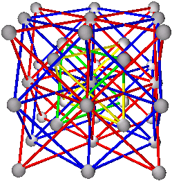
Figure 28. The bcc lattice with 4 fcc lattices and all the interconnecting nets.


Overview and Conclusion

This exploration of the patterns in sphere packing was confined to the cubic closest packing branch and we only explored the growth of patterns from the face centered cubic (fcc) lattice to the body centered cubic (bcc) lattice. The evolution from fcc to bcc structures.

Most of the patterns exhibited here are known patterns, but often only partially observed.

In review, it became apparent that Fuller’s use of concentric pattern growth denoted in frequencies, in the isotropic vector matrix, was a key to facilitating my finding the 4 fcc lattices. I identified the other 3 fcc lattices from the growth patterns of the isotropic vector matrix which I labeled the cuboctahedral D fcc lattice.

The face center cubic (fcc) lattice, with emphasis on the 8 spheres at the corners of the cube and the 6 spheres at the center of the cubic faces (the octahedron), is the octahedral C lattice.


Only recently I learned that Richard Hawkins had identified 4 interpenetrating rhombic dodecahedral lattices from a different path. “I arrived at this understanding by realizing that one coupler can integrate either whole or half into six different rhombic dodecahedral domains in an RD packing and that since the domains on either side of the couplers 2 rhombic equators are part of the same lattice, there are four rhombic dodecahedral lattices in allspace.” R. Hawkins, 2003. You may view his work here.


It is heartening to see that others have come to the same conclusions from different paths.


We notice that different patterns of various combinations of fcc lattices, including the 4 fcc lattices correlate to known structural patterns of elemental and compound chemical structures. A hierarchy between the different patterns was established by showing that they could be derived from the associations of the 4 prime fcc lattices. This followed the order of the simpler to the complex by adding two, three, and 4 lattices together.

We note that in the evolutionary patterns from fcc structures to bcc structures (as shown in this paper) the original length between sphere centers of the fcc lattices remained the same. What this means is that the size of spheres decreased with each structural combination. If the sizes of spheres were to have remained the same the overall structure would have expanded, i.e. the packing would be less dense. In reality the combinations can be of different size atoms, or variations on the sizes of atoms such as a decrease in size due to added structural connections.


As proposed by Donald Ingber in “The Architecture of Life” we found that the underlying principle of tensegrity does extend to the assembly of atoms. That the new interconnections between the self-assembly of atoms, as in compound structures, work together with the original structural systems to form a new tensegrity system.

It is proposed by R. Chu that synergy could be associated with the added interconnections in the new compound structures, in particular, the new structural elements of the new tensegrity system. This was first shown in Fig. 15a.

The above implies that, in compound structures, the parts of the new system still maintain their original structural integrity. If this is true it would mean that some chemical elements, that exhibit compound patterns, would have differences between the atoms. I.e. diamond structures are composed of two fcc lattices, this could mean that there are two kinds of carbons, and bcc structures are composed of 4 fcc lattices, etc…

When we look at the structures of the chemical elements we find that the three most common structures are hcp, fcc, and bcc. From Table 1.1 of “Bonding and Structure of Molecules and Solids” by David Pettifor (1995), we find that, out of the 92 elements: 25 are hcp type, 20 are fcc type, 12 are bcc type, 3 are diamond type, one is simple cubic type, and 31 are of other types.

Towards the end of this exploration it became evident that there are many parallels with Fuller’s quanta modules, which are being explored by Richard Hawkins.

Further explorations of structural patterns derived from Fuller’s isotropic vector matrix could extend our knowledge of the evolution of structures.


January 21, 2003


______________________________________________________________________________________________


Previous Page Home Page Page 1, 2, 3 Next Page

Mapping the Hidden Patterns in Sphere Packing(3)

Previous Page Home Page Next Page

Mapping the Hidden Patterns in Sphere Packing


by Russell Z Chu


Combinations of 3 fcc lattices


There are four possible combinations of 3 fcc lattice connections. See section on Connections between 4 fcc lattices.


1. A+B+C
2.
A+B+D
3.
A+C+D
4.
B+C+D


Due to the increased complexity of patterns, not all the lattices are being shown at the same time. I also tried enhancing some polyhedral faces with color. All of the patterns, shown in this paper, are taken from one single computer model separated into 1, 2, 3, and 4 frequency models. They all contain the following patterns in them, the 4 fcc lattices, the 2 cubic nets and the 4 diamond nets.

The rhombic dodecahedron nets, that we are going to see below, are combinations of 2 diamond nets. The two colors of the rhombic dodecahedron net are the same as the color of the diamond nets. See color below the color chart.


The color code used for lattices and nets:


The 4 fcc lattices:
  • Tetrahedral A lattice (yellow)
  • Tetrahedral B lattice (green)
  • Octahedral C lattice (red)
  • Cuboctahedral D lattice (blue)


The 2 cubic nets:
  • Cubic AB net (black) from the A+B lattice combination.
  • Cubic CD net (Aqua) from the C+D lattice combination.

The 4 diamond nets:

  • Diamond AC net (blue) from the A+C lattice combination.
  • Diamond BC net (gray) from the B+C lattice combination.
  • Diamond AD net (aqua) from the A+D lattice combination.
  • Diamond BD net (purple) from the B+D lattice combination.

The Rhombic Dodecahedron Net structural growth patterns
Also associated with Fluorite type structures.

Chart 4.


Figure 20a, 20b, 20c and 20d.


Figure 21a, 21b, 21c and 21d.


Figure 22a, 22b.


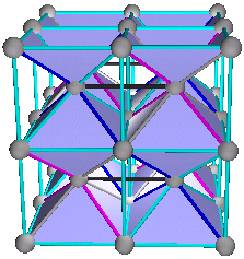
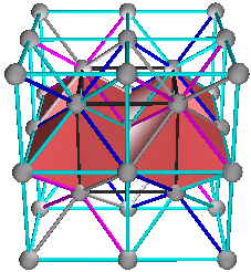
Fig. 20a is showing the first possible rhombic dodecahedron. The rhombic dodecahedron is a compound structure. It takes three different fcc lattices to make a rhombic dodecahedron. As shown at top of Chart 4, it is a combination of A+B+C lattices. The two diamond nets are the blue AC net and the gray BC net. The diamond nets are the same as the diamond nets shown in the previous diamond net patterns.

In the first row of figures, only the rhombic dodecahedron nets are being shown. Not shown are the 3 fcc lattices and the other cubic net.


All 4 combinations shown above are rhombic dodecahedron nets. It becomes more apparent when looking at the second and third row. The first row is a 2 frequency cube grid, the second row is a 3 frequency cube and the third row is a 4 frequency cube.


In the first column, the combination A+B+C lattices has a rhombic dodecahedron at the center of the cube, which is the origin, the location of the first sphere of the D lattice. As the structure grows to the 4 frequency level there will be 12 more rhombic dodecahedrons, one attached to each face of the original rhombic dodecahedron. If this reminds you of the cuboctahedron you are right, it has the same orientation as the cuboctahedral D lattice.


Next in the combination
A+B+D lattices there are six partial rhombic dodecahedron with their 4 edge corner sharing the origin. Note that in Fig. 21b the 6 partial rhombic dodecahedron’s openings are oriented towards the faces of the cube. They make the octahedron. They have the orientation of the octahedral C lattice.

The third combination of
A+C+D is easier to see. There are 4 rhombic dodecahedrons, they make the shape of a tetrahedron. It is in the orientation of the tetrahedral B lattice.

In the last combination
B+C+D it is also 4 rhombic dodecahedrons and this time it is in the tetrahedral A lattice orientation. It is possible to tell which tetrahedral orientation it has because I kept the orientation of the model the same throughout this project.

Some emerging patterns


The orientation pattern – if we look at the A+B+C lattice combination we see that the D lattice is missing and that happens to be the orientation pattern of the rhombic dodecahedrons. We have a rhombic dodecahedral net in the pattern of the cuboctahedral D fcc lattice. They are closest packing. The same follows for the other 3 combinations. We note that the rhombic dodecahedrons are empty. We will see next that in the last combination A+B+C+D that the D lattice will occupy the centers of the rhombic dodecahedral voids.


This is the 1st occurrence, in this system, of a polyhedron adopting the fcc lattice pattern. We know that others like icosahedrons and fullerenes can adopt the the structure of fcc pattern.


The rhombic dodecahedron net is the new set of repeating patterns of 4 fcc lattices.


Rhombic dodecahedron tensegrity


Figure 23.

We are looking at the 3 fcc lattices A+B+C (yellow, green and red), the cube net (black), and the rhombic dodecahedral net (blue). Again this is a tensegrity structure and it is increasingly more complex. With each added layer there is an added web of connectivity. We can see how much information we are missing when we look at this structure as only a rhombic dodecahedral net or a cubic net.


January 21, 2003

______________________________________________________________________________________________

Previous Page Home Page Page 1, 2, 4 Next Page

Viewing Buckminsterfullerene as a Tensegrity Structure

Viewing Buckminsterfullerene as a Tensegrity Structure

by Russell Z Chu
February 23, 2003


The representation of the Buckminsterfullerene (Carbon 60) as a truncated icosahedron is structurally unstable. Likewise the cube is structurally unstable and it could be stabilized by introducing diagonal tensional elements at the faces or viewed as a compound structure of two tetrahedra with the cube as tensional elements.


I came to the understanding of Fullerene tensegrities from my research of crystalline structures in “Mapping the hidden patterns in sphere packing”. In this research I realized that a stable cubical structural system could be viewed as a tensegrity system. That there are secondary structural elements that account for stabilizing the primary unstable system.


With this understanding I decided to look at C60 for the secondary structural elements that would stabilize its primary truncated icosahedron structure.


The figure above is a screen capture of a model built with SpringDance 3D program.


The primary structure of C60 in red color is what we are used to seeing, the truncated icosahedron.


The secondary structural elements are tensional elements. They are the yellow tension elements inside the pentagons and the aqua tensional elements inside the hexagons. These tensional elements are all the secondary connections from one carbon atom to the next nearest atom. The primary connections are the red truncated icosahedron.

This tensegrity system is similar to the bicycle wheel, but instead of spokes it is a spherical tensional net. The bouncy property of C60 can be attributed to the tensegrity structural system.


Thursday, July 29, 2010

Mapping the Hidden Patterns in Sphere Packing (2)

Mapping the Hidden Patterns in Sphere Packing

by Russell Z Chu

Connections between 4 fcc lattices

Secondary structural systems


Figure 13.

Fig. 13 is showing the various possible relationships between the 4 fcc lattices. These are tetrahedral relationships.

The primary system is the face center cubic lattice (fcc), which is composed of four fcc lattices- the tetrahedral A lattice, the tetrahedral B lattice, the octahedral C lattice and the cuboctahedral D lattice.

The secondary systems are compound structures of the 4 primary fcc lattices.

To follow are all the possible combinations, or relationships between four systems.

Between four systems there are 6 possible edge connections of two systems, 4 possible triangular connections of 3 systems, and 1 tetrahedral connection of all four systems.

Six - two fcc lattice connections: A+B, C+D, A+C, A+D, B+C, B+D. They are divided into two groups:

  1. (2) Simple cubic structures: A+B and C+D
  2. (4) Diamond net structures: A+C, A+D, B+C, B+D

Four - three fcc lattice connections: A+B+C, A+B+D, A+C+D, B+C+D.

One - four fcc lattice connection: A+B+C+D.

It appears that nature tries all possible combinations. Structures evolve through generations of self assembly.

We do see unexpected results when we combine the 4 fcc lattices. Unexpected because we are not used to getting different results when making similar operations except in chemistry, where the synergistic combinations create added value to the new system that are greater than the sum of the individual parts considered separately.

We find that, within the 6 - two fcc lattice combinations, there is a division into 2 cubical net combinations and 4 diamond net combinations.

If we look back at Chart 1 we notice that there are some patterns that might be significant in predicting future patterns:

  1. Frequencies of A and B go into each other.
  2. Frequencies of C go into D only.
  3. Frequencies of A go into C and D.
  4. Frequencies of B go into C and D.

From the combinations of 2 lattices we have the 2 cubic patterns and the 4 diamond patterns.

Combinations of 2 fcc lattices

Chart 2. The simple cubic structural growth patterns


Chart 2 and Chart 3 go together.

Chart 2 is showing the growth patterns of the compound structures A+B and C+D (simple cubic). This chart represents the simple cubic group, the other group of 2 fcc lattices is the diamond net structures shown in Chart 3.

The patterns are being shown in a schematic form of the cube, it is one of the faces of the cube. Please compare the schematic pattern with Fig.15a, 15b, and 15c. The black squares represent the A+B cubic net, the yellow diagonals represent the yellow tetrahedral A lattice and the green diagonals represent the green tetrahedral B lattice.

The same schematic pattern applies to the C+D cubic net in Fig. 15b. The aqua squares represent the C+D cubic net, the red diagonals represent the red octahedral lattice and the blue diagonals represent the blue cuboctahedral D lattice.

We can see from Chart 2 that the cubical frequency progression jumps back and forth from cubic AB to cubic CD. The cubic AB (black) are all odd frequencies and cubic CD (aqua) are all even frequencies. This alternating pattern is related to the caging pattern or nesting of cubes, as shown in Fig. 15c.

The simple cubic pattern is also the same as the octahedral void filling pattern. When A and B lattices combine they can be seen as a simple cubic net or the vertexes of one lattice occupying the center of the other lattice’s octahedrons. This also applies to C+D combinations.

Simple Cubic Structures

A+B and C+D

Two interpenetrating fcc lattices or simple cubic structure


Figure 14a, 14b.

Fig. 14a is the simple cubic structure of A+B.

Fig. 14b is the simple cubic structure of C+D.

The Unified View

The cubic net and the 2 interpenetrating fcc lattices.


Figure 15a, 15b and 15c.

Fig. 15a is the unified view of the AB cubic net with the fcc A lattice and the fcc B lattice.

Fig. 15b is the unified view of the CD cubic net with the fcc C lattice and the fcc D lattice. It is a 2 frequency cube with 8 unit cubes.

Fig. 15c is the 3 frequency cube (back) caging inside the 2 frequency cube (aqua). It shows the alternating pattern between frequencies.

It is important to note that the integrity of the structural system of each lattice, their pattern, are maintained even though they have combined into a new system.

Tensegrity and Synergy

The unification of the 2 interpenetrating fcc lattices and the cubical net allow us to see the simple cubic structure as a tensegrity structure. With the tetrahedral A lattice and the tetrahedral B lattice bound together by the cubical net Fig. 15a. Fig. 15b is the same tensegrity structure as Fig. 15a.

In Fig. 15a we can see a yellow tetrahedron, a green tetrahedron and a black cube. What we have is a tensegrity structure where the yellow tetrahedron and the green tetrahedron become compression members when the cube net goes into tension. It may be easier to visualize the face of the cube as a tensegrity, with the 2 diagonal rods secured at the ends with a string, in the shape of a square. These stable square faces then can be assembled into a tensegrity cube.

When the edge length of the cube net decreases (go into tension) the edge length of the tetrahedral A and B lattices would tend to decrease (go into compression) until a new equilibrium is established. This is a dynamic structural view of two chemical elements of fcc lattice type brought together and forming a simple cubic net tensegrity structure. We can visualize the expansion and contraction of materials with change of energy, temperature, pressure etc...

Fig. 15a shows a 1f cube, it is the first possible cube. The cube exists only as a compound structure.

Synergy is defined as the behavior of whole systems unpredicted by the behavior of their parts taken separately (Fuller, Synergetics 101.01).

Syn.er.gism – the joint action of different substances in producing an effect greater than the sum of the effects of all the substances acting separately (dictionary).

I am proposing that the added effect of synergy can be associated with the added structural patterns, tension components, of tensegrity structures. In the case of the simple cubic structure it is the cubic net AB added to the A and B fcc lattices, as shown in Fig. 15a and 15b.

This effect of synergy and tensegrity could be seen further in the structures to follow.

Tensegrity: "The word 'tensegrity' is an invention: a contraction of 'tensional integrity.' Tensegrity describes a structural-relationship principle in which structural shape is guaranteed by the finitely closed, comprehensively continuous, tensional behaviors of the system and not by the discontinuous and exclusively local compressional member behaviors. Tensegrity provides the ability to yield increasingly without ultimately breaking or coming asunder." (Fuller, Synergetics 700.011)

For more on tensegrity: in ‘The Architecture of Life’ Dr. Donald E. Ingber wrote about ‘What is tensegrity’ with great insights.

All structures are tensegrities. What differentiate tensegrity structures are the different levels of separation between the patterns of compression members and the patterns of tension members within each structure. We start from the prime structural systems where the patterns of tension and compression (push and pull) are the same, the structural members are both compression and tension members, as we see in the fcc lattice (structural systems), next we see a separation of tension and compression patterns as in the compound structure of simple cubic as shown above Fig. 15a, b. This progression increases until compression members do not touch each other or we have continuous tension and islanded compression.

The different degrees of separation in tensegrities give different qualities to structures, from rigid to bouncy.

The minimum omni symmetrical prime structural systems are the tetrahedron, octahedron and icosahedron. Whenever we work with cubes, dodecahedra and other non-triangulated polyhedra we would be able to find the other parts of the structural system that have been overlooked.


Chart 3. The diamond net structural growth patterns

Chart 3 is a graphical representation of the 3D structures shown below in Figures 16 through 19. The squares are a representation of the tetrahedrons that are occupied by the diamond net.

We can see that all 4 combinations contain tetrahedral A or tetrahedral B lattice. The tetrahedral lattice influences the alternating pattern and 3D mirror like pattern between the A and B columns.

The 2f A+C is shown in Fig. 16b and 17a.

The 2f B+C is shown in Fig. 16c and 17b.

The 2f A+D is shown in Fig. 18a and 19a.

The 2f B+D is shown in Fig. 18b and 19b.

The 3f A+C is shown in Fig. 17c.

The 3f B+D is shown in Fig. 19c.


Diamond Net Structures

Fcc lattices A+C and B+C


Figure 16a, 16b, 16c, and 16d.

Fig. 16a is showing the diamond net (blue). We can see the diamond net in Fig. 16b connecting the yellow and red lattices.

Fig. 16b is showing the unified view of the 2 interpenetrating fcc lattices (A+C) with the blue diamond net. When we compare with Fig. 14d we see that it is the same structure except that it is rotated to the point of view of the tetrahedron. It is easier to see the yellow 1f tetrahedron caged inside the red 2f tetrahedron.

Fig. 16c is showing the 2 interpenetrating fcc lattices (B+C) with the gray diamond net. Notice that lattice B occupies the tetrahedrons not occupied by lattice A in Fig. 16b.

Diamond net pattern is the same as tetrahedral void filling pattern. The 2 interpenetrating lattice method let us see why some tetrahedrons are not filled and exactly where they are filled or not.

Tensegrity relationships

Looking at Fig. 16d we see the yellow tetrahedron caged inside the red 2f tetrahedron from the C lattice. The yellow tetrahedron does not touch any part of the red tetrahedron. We see the blue diamond net connecting the two fcc lattices together. This is also a tensegrity relationship where the 2 fcc lattices would contract when the diamond net contracts or when the diamond net goes into tension the 2 lattices would go into compression. Which also means when the two fcc lattices expand it would stretch the diamond net and if it stretches beyond the bond can hold the compound structure would fall apart, melt, dissolve, etc…


Figure 17a, 17b and 17c.

Fig. 17a is the 2f A+C structure in Chart 3. The tetrahedral bond is emphasized so it could be seen more clearly. The cubic grid is to help visualize spatial location. See Fig. 17c which does not have the aid of cubic grid.

Fig. 17b is the 2f B+C structure.

Fig. 17c is the 3f A+C structure.


Diamond Net Structures

Fcc lattices A+D and B+D


Figure 18a, 18b.


Fig. 18a is showing the A+D fcc lattices and the interconnecting diamond net (aqua), same as Fig. 19a.

Fig. 18b is showing the B+D fcc lattices and the interconnecting diamond net (purple), same as Fig. 19b.


Figure 19a, 19b and 19c.

Fig. 19a is showing the 2f A+D with the tetrahedral or diamond net emphasized for better seeing.

Fig. 19b is showing the 2f B+D with the diamond net.

Fig. 19c is showing the 3f B+D with the diamond net. Notice the caging at 2f the D lattice is outside and at 3f the B lattice is outside.

January 21,2003

______________________________________________________________________________________________

Previous Page Home Page Page 1, 3, 4 Next Page